

A brief introduction to CMOS photosensitive chips
1.Typical CMOS image sensors can be divided into several modules: pixel array, control register, timing control logic, analog signal processing, ADC analog-to-digital conversion, and DSP
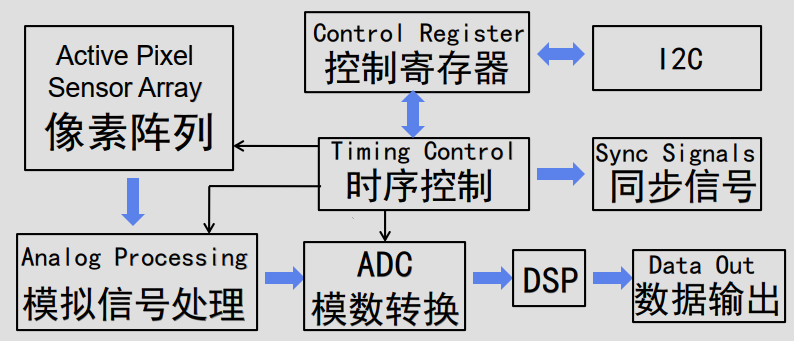
.ADC analog-to-digital conversion, converting analog signals into Raw Bayer digital image signals;
.The timing control module controls and outputs various clock signals required for sensor operation, including Vsync (field synchronization signal), Hsync (frame synchronization signal), pclk (clock signal);
.Control registers and make some settings for sensors through I2C, such as image output size, PLL settings, effect settings, etc.
.The Active Pixel Sensor Array consists of three main components for each pixel unit: Micro Lens, Color Filter, and Photo Diode, as shown in the figure below.
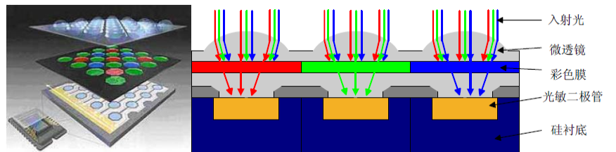
.Micro lenses are used to converge incident light, increase the angle range of incident light, expand the photosensitive area of a single pixel, and provide greater compensation for incident light intensity.
.Color filters typically come in three colors: red, blue, and green, selectively passing through red, blue, and green light.
Due to the Color Filter, most sensors output raw images in a Bayer pattern, as shown below, with 2 * 2 pixels as a unit and 4 different arrangements between pixels: RGGB、BGGR、GRBG、GBRG。
Question 1: Why are red, blue, and green colors used?

Early scientific verification showed that various colors of light commonly found in nature can be obtained by mixing the RGB primary colors in different proportions. Similarly, most colored light can also be decomposed into three colors: red, green, and blue.
This is the principle of RGB primary colors, which is C=a R+b G+c B, a , b , c ≥ 0 C = aR+bG+cB, a,b,c≥0C=aR+bG+cB,a,b,c≥0, Among them, C is any color, and a, b, and c are the weights of the three primary colors.
The use of three primary colors also conforms to the physiological characteristics of human cone cells. Cone shaped cells contain three different types of color sensitive cells, namely red cone shaped cells that sense long wavelengths, green cone shaped cells that sense medium wavelengths, and blue cone shaped cells that sense short wavelengths.
Question 2: Why does Color Filter distribute R: G:B=1:2:1?
G adopts a higher sampling rate because the peak of the human eye's brightness response curve is closer to the green frequency range, and brightness information can be obtained through the G channel. Brightness information is the most important component of an image, so two G's are more conducive to the transmission of brightness information and reduce distortion. Therefore, leaning towards green in sampling is beneficial for the image's quality details.
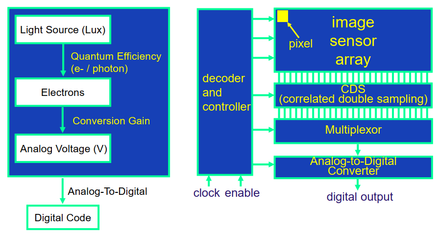
Photodiodes are used for photoelectric conversion. Photodiodes cannot sense the color of light, only the intensity of light.
When light shines on the surface of a photodiode, it excites electrons, and the number of electrons is proportional to the intensity of the incident light.
For example, in the schematic diagram of the structure of the red photosensitive pixel unit in the above figure, the micro lens converges the incident light, and the red film filters out other colors of light, leaving only red light projected to the photodiode. The photodiode converts the received light signal intensity into a corresponding voltage signal output, which indicates the strength of the red light component in the incident light at that point.
The signal sampling process is roughly as follows:
2. Some characteristics of CMOS sensors
2.1 Noise
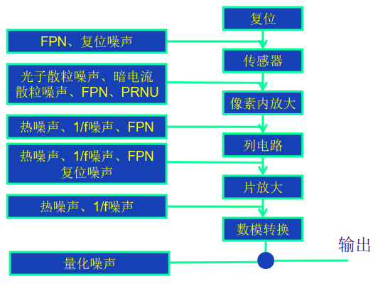
The main sources of noise in CMOS sensors are the photodiodes of pixel photosensitive units, field-effect transistors, and other noise generated during the operation of image sensors.
The noise generated by photodiodes includes thermal noise, shot noise, composite noise, and current noise.
MOSFETs, including amplifying MOSFETs and MOSFETs used for simulating switches for row and column selection, mainly cause thermal noise, induced gate noise, and current noise.
The CMOS image sensor composed of photosensitive array and MOSFET may also cause other noises during operation, such as reset noise and spatial noise.
In the signal sampling process, there is a CDS (Correlated Double Sampling), which is mainly used to reduce fixed pattern noise FPN. The reason for the generation of fixed pattern noise is that the output signal produced by the same beam of light shining on two different pixels is not completely the same.
Double sampling is the process of first reading out the charge integration signal generated by illumination, temporarily storing it, resetting the pixel unit, and then reading the output signal of this pixel unit. Subtracting the two results in an image signal, which can effectively suppress fixed pattern noise.
2.2 Dark Current
The leakage current generated by a CMOS sensor in the absence of light is called dark current.
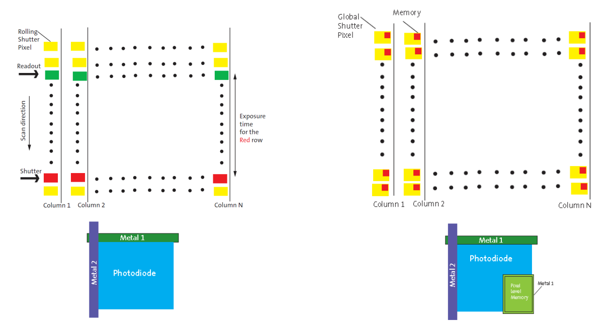
2.3 Exposure Type Shutter Type
The exposure methods for CMOS sensors include field exposure Global shutter and line exposure Electronic rolling shutter.
Line exposure Electronic rolling shutter, line pixel alternating exposure mode, with different start and end times for each pixel exposure line. Capturing the scene of fast-moving objects can cause image distortion and distortion.
Global shutter for field exposure, all pixel exposures start and end at the same time. Memory is required to store pixel values, which incurs high cost.
2.4 OTPM
To eliminate the differences in image effects between cameras and maintain consistency, it is necessary to calibrate and calculate each module separately, and store the calculated data in the sensor/eprom.
The main reasons for the differences in image effects between cameras are: sensor、Lens、IR-cut、VCM、driver IC、 Differences generated during the production assembly process
2.5 Dynamic Range
Dynamic Range, in electronics, refers to the range covered by the signal limit that the receiver can receive. For CMOS sensors, it is the detailed detection of bright and dark areas (also known as the extreme manifestation of black and white).
Dynamic Range refers to the sensor's ability to sense changes in the color tone of the original object, measured in dB. The higher the value, the more favorable the image quality.
The dynamic range definition formula for sensor: ![]()
It is actually a multiple relationship between the maximum accumulated charge and the minimum noise charge of the sensor.
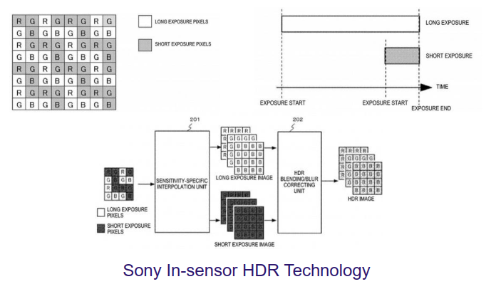
HDR-High Dynamic Range, High dynamic range, the common HDR method involves synthesizing multiple images with different exposure times, but the speed is slower.
There is another type of HDR where the chip itself outputs HDR images, and the more common ways are:
Different exposure times are used between adjacent pixels;
It is necessary to first collect data for each row of pixels at different exposure times, and then output the data after the exposure is completed. This method requires an additional data buffer area to temporarily store the data.
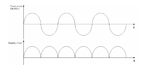
2.7 Auto Flicker oscillation
Due to the fact that the brightness of the light source varies periodically with alternating current, if the exposure time is not an integer multiple of the brightness cycle, the camera will show alternating light and dark stripes in the image when facing the fluorescent lamp, which is called flicker.
How to eliminate Flicker?
The AC frequency is divided into 50Hz and 60Hz, corresponding to minimum brightness periods of 10ms and 8.33ms, respectively. In order to ensure that the light energy received by each row of pixels during the same exposure time is periodic, the exposure time needs to be adjusted to an integer multiple of its minimum brightness period, which can eliminate Flicker.
If the exposure time is less than the minimum brightness cycle, Flicker cannot be eliminated.
2.8 Sensitivity
Sensitivity is the signal current generated by an image sensor per unit of light power, which is the responsiveness of the image sensor, i.e. the effective signal voltage obtained per unit exposure. It reflects the sensor's ability to sense light.
Sensitivity calculation formula:![]() is the unit of brightness, measured in candela per square meter.
is the unit of brightness, measured in candela per square meter.


